Categories
CALL FOR ACTION SOLUTIONS TECH

SECURING THE VOTE – WHAT OUR ELECTION SYSTEM DATABASE SHOULD LOOK LIKE – updated 11/02/24

With the influx of illegal migrants and in view of the wide spread fraud in the 2020 election, a great concern has arisen regarding the integrity of our national election system. What is herein is to suggest a solution to that dilemma.

Our current election system is a piece of crap. It is a hodgepodge of manual and batch systems ripe with fraud. That a secure online real time election system “database”  has not been made available by now is an absolute crime.

A DATABASE PRIMER:

What is a “database”, you ask? It is an electronic filing organization that provides entree point access to “External-Master Records” which in turn provide navigatable link chains to more “Internal-Detail Records”. It is a piece of electronic infrastructure contained on a serving computer. And just like a geographic infrastructure requires an accessibility map, so does a database.

A database “schema diagram” is a map of the external access to & internal connectivity  between “record-types” within a database. Each record-type is represented by a big rounded rectangle, aka, box, in the database schema diagram. The external access to a record-type is represented by a small arrow headed by an oval pointing into the record-type.  And internal connectivity between record-types via link chaining is represented by a line between rounded boxes, where the line may or may not be terminated with a directional arrow. 

As a side note, think of a “record-type” as a single template or layout representing any number of records consisting of the same record format. If you wish, you can call a “record-type”  a “record-template” . A “record” is  defined as a fixed length string of data broken into contiguous fixed length “data fields”, with each “data field” consisting of a contiguous fixed length string of textual characters.

Also as a side note, “link chaining” is a method connecting records together wherein the first record is the master record that contains the address location of the first detail record, which contains the address location of the next detail record, and so on. An analogy would be the postman’s route beginning at the first house in a given block which contains the address of the next door house in the block, etc.

Here is an example of what a very elementary database schema map looks like in figure A.

FIGURE A.

So how do we interpret this diagram?

Looking at the  very lowest box, it is a detail record-type subordinate to both of the upper two master record-types, because it participates in link chains from both of the upper two record-types as represented by the two lines connecting it to the two upper boxes. In such a master-detail relationship, there are  generally many detail records per each master record. 

The top 2 boxes are connected by a single link chain which is represented by the line  between the 2 boxes, thus making the lower of the two boxes a detail record-type subordinate to the upper master record-type.  Both of the upper two record-types  are externally accessible via a unique key field  as indicated by an arrow headed by an oval pointing into the box.  The upper box does not participate as a detail in any link chain. Therefore, it is said to be an “external master” record-type. But the middle box is both externally accessible & participates as a detail in the link chain connecting  it to the upper box. Therefore, it is said to be a “hybrid master” record-type. 

So we can now see record-type accessibility, hence individual record accessibility,  is accomplished in one of two ways:
1) externally via a unique key field, such records being called “external master” records, or
2) internally via link chains which are data fields within each record pointing from one record to the next, such records being called “internal detail” records. There can be any number of different link chain data fields within any record-type.

In addition, you should note that two of the link chains are terminated with a downward arrow to indicate a 1-way dead-end, which  means the master record is not retrievable from any detail record in the link chain. You should also note that one link chain has no arrow indicated at either end of the line which means the master record is directly retrievable from any detail record or indirectly by traversing the link chain either way, downward or upward. In  other words, it is a 2-way street.

But record-type access is only part of the story.  Equally important is the principle of full or partial record “update permissions” which is key to protecting the data within the database. It is one thing to only see data. It is quite another to be able to add, change or  delete data. A person’s logon should contain an indication of their level of update permissions. This is what separates administrators from non-administrators. And in our election system,  it is what separates citizens from non-citizens.

Hopefully by now it is intuitively clear on how to read a database diagram. But if you still feel uncomfortable with what you have read so far, you can skip to the last section entitled HOW TO READ THE DATABASE at the bottom of this post. We proceed from here to explain  the detail workings of the database.

#jmp1

THE OVERALL ELECTION SYSTEM DATABASE:

Here in figure B  is a schema diagram of what an overall National Election Database should look like. You should note at the top are numbered sectional identities.

FIGURE B.(Too small? On your phone, expand it. On your computer, right click and open image in new tab. Or download & save it to resize.)

Key to understanding this map is the concept of “governance levels”. We all understand the divisions within our own government as being  federal, state, county, & city which represents the most geographically remote part of our government that includes the progressively nearer parts of our government. These we call the governance levels each of which can be uniquely identified by a single digit. 

And each governance level maintains its own records. When these records are all thrown into one big pile, we need to know who can do what with respect to altering these records. This necessitates the need for a way of identifying  who has the permission to update records at what governance level.  Because any one person should not have update permissions to records within more than one governance level, it should be sufficient to tag any one person’s update permissions with the digit assigned to the governance level. But sometimes, as in the case of the various levels within a state, a 2 digit suffix to the permission-level is required to identify the state.

In this election system, I have assigned  numbers to the governance permission-levels as follows:
0 = non-citizen
1 = citizen
2 = citizen precinct-admin
3 = citizen city-admin
4 = citizen county-admin
5 = citizen state-admin
6 = citizen federal-admin
This, in essence, identifies the basic workings of this online election system database.

All users will initially be assigned  a permissions-level = 0, meaning they have no update ability to any part of the database.  After that, any user who is qualified to vote, including any administrator,  must provide PROOF OF CITIZENSHIP,  which subsequently grants them a  user’s permissions-level higher than 0, meaning they have update ability to those parts of the database as specified by their permissions-level. 

 State governments should not be assigning a permissions-level higher than 0 simply based upon a DMV ID or social security number, because these are issued to citizens and non-citizens alike and are not proof of citizenship.  And absolutely no state should be issuing ballots in any form to anyone who has not submitted a validated citizen request.  Capisce?

The database diagram, ie, map, can be seen as divided into four sections:

1. The left section 1 represents all user logons (including non-citizens,  citizen voters, & citizen administrators)  & their online requests records for access & update permissions-level to the appropriate governance-level records in section 3 of the database. 

  2. The middle-left section 2  represents the administrator control area which provides the mechanism required for validating & identifying citizen logons as distinct from non-citizen logons, as well as identifying citizen logons as distinct from citizen administrator logons.

3. The middle-right section 3 represents the government’s organizational hierarchical levels, ie, governance levels, from the top-down and associated election data. 

4. The right section 4 represents the area where administrators create linkages from a citizens’s request to:
a. be linked to a government office as a candidate,   or
b. access a ballot based upon his submission of a ballot request.
These requests are serviced  by state election administrators who are basically online voter registrars. 

The following discusses in detail the workings of each section.

Section 1 – USER LOGONS & UPDATE PERMISSIONS:

This section 1 is the  left-hand side of the database map which represents the part of the database that contains all users’ (including all administrators’) logon records. Anybody can create a user logon record with password,  regardless of citizenship.  In creating a logon, the user must submit his birth date  &  the last four digits, if not all, of his social security tax-id number, the combination of which should uniquely identify his logon to any election administrator & remain relatively unchanged, even if he moves to a new state.  He should also include his zip-code which he should keep up-to-date at all times.

For privacy reasons, access to his user’s logon record is restricted to the individual user who owns the logon. This is to protect the user’s profile from being exposed, including his voting record.  Absolutely no one will have access to the user’s logon record & profile.  Any data needed by administrators will be plugged into the user’s subsequent request record(s) which will be accessed and updated by administrators. 

Even though a user has created a logon, it does not mean he has update-permissions to any part of the database other than his own logon area. Such update-permissions can only be obtained by submitting a first one-time request record along with proof of citizenship in the form of a picture plus a passport-id or medicare-id or birth-certificate or naturalization-papers. Such submission can be in-person or via online. 

Upon entry of the request into the database, a  self assigning SYSTEM-USER-ID record will be automatically created for his logon having a permissions-level = 0, meaning he has no update permissions.  His unique system-user-id will be formed from the combination of his birth date & last four digits of his social security number to become what might be called a preliminary “voter-id”. 

In conjunction with his first one-time request record, the request record will be linked into a federal or state administrator work-list file to notify administrators of the request. And upon approval of his proof of citizenship by an administrator, his permission-level will be appropriately set higher than 0, thereby granting him the update ability he requested. If the user fails to qualify as a citizen, his newly created  system-user-id will remain at permissions-level = 0 , meaning he has no update=permission to the  rest of the database.   Otherwise, he will be assigned a permissions-level number higher than 0.

There are three  types of  a user requests, any of which can be the first one-time request.
a) An ADMINISTRATORS PERMISSIONS REQUEST is simply a request to change ones logon permissions-level to be changed to higher than 1. 
b) A CANDIDATE REQUEST can be made by any permission-level greater than 0. It must specify the specific Nation-ID, State-ID, County/ District-ID,  City-ID & Office-ID  for which the user seeks to run.  The administrator processing the request must link the request  record to the appropriate year & office-id records.   
c) A BALLOT REQUEST can be made by any permission-level greater than 0. It is simply a request by a user to his lowest level of local election administration to create link chain from his request record to the candidate link records applicable to his geographic area for the year in question. Therefore, he must include his zip code in making the request. 

Each user request subsequent to the first request must be validated by the assigned permissions-level in his first one-time request record.  

Of course, not every body may have a cell phone or computer which is quite unlikely.  In this case they should be able to find a public internet terminal like a library or the county registrars office. In the absence of that, they should obtain a paper ballot, but only upon proof of citizenship which could include having a social security number or some other form of federal id that the user has in mind.

Section 2 – THE ADMINISTRATION CONTROL SECTION  FOR SECURING THE ELECTIONS. 

This section 2 is the middle-left section of the database schema & represents the area of the database which houses  the  externally accessible system-user-id records  created as described in section 1.

The following applies to this section.

a. Once a user’s  system-user-id record  is created by submitting his first one-time request, it will be impossible for another user to create a duplicate system-user-id  record.

b. The system-user-id  record will be qualified by the assignment of a permissions-level number to identify non-citizens from citizens & regular citizens from administrators.
The permissions-level numbering is as follows:
0 = non-citizen (no update permissions)
1 = citizen
2 = citizen precinct-admin
3 = citizen city-admin
4 = citizen county-admin
5 = citizen state-admin
6 = citizen federal-admin

c. The first creation of a system-user-id will assign a permissions-level = 0  & remain so until proof-of-citizenship is approved. 

d. State level administrator permission-levels 2 through 5 require a 2-character State-ID suffix appended  to restrict their update permissions  to the state in which they are qualified to serve. For example, we do not  want an administrator in Georgia making changes in Arizona.  For the rest of this document, we will assume that the permissions level for a state administrator includes that state suffix.

Any administrative level within a state can service any user’s request within the same state  for  a permissions-level change to 1. But any user’s request for a permissions-level greater than 1 must be serviced within the state & not by any administrative level higher than the permissions-level requested.  Any user’s request to be a candidate for office must be serviced within the state & not by any administrator other than an administrator at the same level as the office. Lastly, any user request for a ballot connection must be serviced within the state at the lowest level of administration available to user’s location.  

e. Federal administrator logons will be flagged as permissions-level 6 & include employees within the Federal Election Commission,  the US State Dept, the Medicare Admin, or the Social Security Admin. All federal administrators must be proven citizens  to have level 6 update permissions. if the feds wish to qualify their administrators permission-level, they can attach a 2 character code suffix to the permissions-level number. It should be noted that the Social Security or Medicare Administrations may invalidate a user’s permissions-level by submitting a record linked to the first one-time request record to indicate a deceased user. 

f. With the exception of initializing identity records below its level,  no administrative level can alter any of the detail records added by the administrative levels above or below its own level.

g. Looking at the database diagram you will note that the users system-user-id record can be linked to either of two header record types. One is a federal administrators work list which queues the feds to a system-user-id that requires attention. The other is the state administrators work list which is a list to queue the state a request requires their attention.  

h. Now turning to the feds work list, it is a file of notifications that queue the feds of items requiring their attention. A new user may have submitted a first one-time request using only a passport, medicare or social security number as proof of citizenship. Such a case should result in an automatic notification being put in the feds work list. Or maybe a user in creating their logon  specified a combination of birth date and last 4 digits of social security number that conflicts with an existing system-user-id. Again, an automatic notification should go in the feds work list.  And yet again, put an automatic notification in the feds work list when a system-user-id  is approaching  the 4-year permissions-level expiration date. Did you hear me say a “4-year permissions-level expiration date”? Yep, you heard right. We just cannot afford to let deceased citizens continue to vote. So why not automatically notify the fed of a possibly deceased voter? 

i. With respect to the state work-list, a work list  for each level of state government needs to be identified & accessed by its permissions-level level number and a combination of State-ID, County-ID, City-ID, & Precinct-ID to facilitate processing of user requests at the correct level.  

j. With respect to processing the previously mentioned requests, due diligence in validating citizenship & existing citizenship currency is of the utmost importance to  prevent any bad actors from trying to game the system & vote as a non-citizen or more than once in any election.

It should be noted that state governments should not be assigning a permissions-level of 1 based simply upon a DMV ID.  Nor should states be issuing ballots without a request from a qualified citizen system-user-id, ie, voter-id.

Paper ballots should be eliminated as much as possible. Ballots should only be given out  in electronic form  to people who have a qualified citizen system-user-id, ie, a voter-id.  

For the purpose of validating new first one-time requests,  any among the Federal State Dept, Social Security or Medicare Admin should be able to confirm citizenship in the absence of proof-of-citizenship documents. For the purpose of validating citizenship currency, the Social Security &/or Medicare Administrations should inactivate any voter-ids of dead people.

For the purpose of preventing bad actors from voting more than once in any given election every voter must issue a ballot request for every election. Validated voters should not have their ballots automatically setup, ie, issued, to them, because they may have moved to another state. This requirement for the voter to submit a ballot request every election year helps to prevent a voter from obtaining more than  one voter-id by changing his logon profile identity, because his previous requests will show his logon was used with another voter-id. However, women who marry should be able to change their name in their logon when they marry.

We must be able to deal with the voter who creates multiple logons. Where he might be able to present different birth dates, he should still be unable to submit more than one social security number in conjunction with the same birth date. And if he randomly picks those numbers, there is a good chance the combination already belongs to someone else

Section 3 – THE ORGANIZATIONAL HIERARCHY & GOVERNANCE LEVELS:

This section 3 is in middle-right part of the database map & represents the identities of our governmental hierarchical levels & their respective offices to be filled by elections.  It should be intuitively clear that within the nation are several states, & within states are several congressional districts and counties, & within counties are several cities, & within cities are several zip codes, & within zip codes are precincts. Excluding the zip-code level, each level is assigned an identity number. It should come as no surprise to see that our assignment of each level’s ID number corresponds to a user permission-level number.  But to be perfectly explicit, start at the national level as level 6 & proceeding down through the levels, each lower level gets tagged with the  next  lower level indicator. As a consequence, we have level 6 being the national level, level 5 the state level, level 4 the county & district level, level 3 the city level, level 2 the precinct level. And again, this leaves levels 1 & 0 representing the individual user logon.

a. GOVERNANCE LEVEL 6 INITIALIZATION: We now turn our attention to the initial establishment of this part of the database.   So we begin with the feds, because they are the keepers of the database, it being on their computer, & because they have ultimate authority regarding citizenship status. The very top master record is the Nation-ID record is assigned a level-ID = 6 & will be created by the feds via a single backdoor logon with permissions-level-6 . This single backdoor logon will be able to service any permissions-level 0 system-user-ids requesting  level 6 permissions as previously discussed, thereby creating more federal administrators. 

b. GOVERNANCE LEVEL 5 INITIALIZATION:
Before we continue any further, we must state this principle. In section 3 any given administrative level may create the master id header records for the entities one level below it’s own level  & provide that level with a single backdoor administrator logon.

Therefore, the feds can create State-ID hybrid master records as detail records to the overall Nation-ID master record, but nothing below those State-ID records. As each State-ID record is created, a single backdoor permissions-level 5 logon for each state will be provided to the lead state administrator for that state. ( Note:This is the one exception to assigning an administrative permissions-level lower than the processing administrator.)

In addition, if the feds are really nice, they might even initialize all system-user-id records setting each system-user-id to permission-level 0 or 1 , even before any real users create their logons. After all, they do have the information to do so, ie, birth date and social security number. But knowing the feds, we cannot count on it. And there really is no need until a user creates a logon.

After initializing the State-ID records,  the feds should not be creating or updating any other records in section 3  or section  4 of the database. They can only update the permissions-level in the user’s-system-id record in section 2 of the database & create, update or delete notice records in their own federal work list.

c. GOVERNANCE LEVEL 4 INITIALIZATION:
We now turn to the state administration level 5 processes with respect to initializing district and county updating records in section 3, the following holds.  In the same fashion as the feds setup the next lower level governance ids, each state’s backdoor level-5 logon will be able to change any level-0 logon to another level-5  administrator logon once the level 0 logon owner submits proof of citizenship either in person or via the logon online administrator request process. And the level-5 administrators will create the County-ID records & District-ID records, along with creating a backdoor level-4 administrator logon for each county. This same cascading process will apply to initializing the lower level  governance ids, ie, county, city & precinct ids.

In a similar fashion, each state’s backdoor level-5 logon will be able to change any level-0 logon to another level-5 or level-4 administrator logon once the level 0 logon owner submits proof of citizenship either in person or via the logon online candidate/ballot request process. Any level-5 administrator will create the County-ID records & District-ID records, along with creating a backdoor level-4 administrator logon for each county.

d. GOVERNANCE LEVEL 3 INITIALIZATION:
In a fashion similar to the state, each county would setup City-ID records, along with creating backdoor level-3 logons to be used by city administrators in conducting its elections.

e. GOVERNANCE LEVEL 2 INITIALIZATION:
In a fashion similar to the county, each city may elect to setup Precinct-ID records, along with creating backdoor level-2 logons to be used by the precinct administrators.

f. OFFICE/PROPOSITION RECORDS:
Obviously for each level of governance from city on up there exists departments & offices with positions to be filled, some of which are filled via elections. And so each level of government is responsible for defining those positions to be filled via election. These are the Office-ID records, and each year some or all of them may have vacancies to be filled by candidates.

Section 4 – TYING USER LOGONS TO THE GOVERNMENT ORGANIZATION & ELECTION RECORDS:

The right side of the database diagram deals with linking the user request record-types to the appropriate area of section 3 . Clearly before a voter can request a ballot, there must be candidates to select from.

This brings us to the creation of a candidate-link record by the appropriate level administrator. And how do we do that? 

A CANDIDATE REQUEST will call out the specific State-ID, County/ District-ID, & City-ID where applicable & the specific Office-ID. Assuming the would-be candidate is qualified & has a valid Voter-ID, the impacted administrator level will create a candidate link record for the year in question, thus establishing his candidacy.

It should be noted that there are times when there are non-candidate measures at the city, county, or state levels to be voted upon. These are identified as Propositions. They are identified in the same candidate link record-type which is accessible via the voter to the same candidate link record-type as used for candidate-to-office links.

A BALLOT REQUEST is simply a request to his lowest level of election administration to create links between his ballot request master & the candidate link records applicable to his geographic area.

VOTING:

The database is now ready for the voter to make his candidate selections by clicking the appropriate candidate-selection button in each appropriate voter-ballot-link record, at which time a write-permission lock is placed on the voter-ballot-link record. This would prevent anyone from changing candidate-selection button and the corresponding link to the selected candidate record.

POST VOTING RECORD ACCESS:

For secrecy/privacy purposes all cast voter-ballot-link records should be locked from updating by anyone other than the voter and as soon as they are counted. With this one exception, all should be able to view any record at any time, thus providing complete transparency and veracity of an election. In other words, everyone can look anywhere but not touch.

TALLYING UP THE TOTALS:

In addition, currency of vote tabulation is essential. As soon as a voter has locked his voter-ballot record, his vote should be counted and tallies by candidate should be made available. Washington DC should be connected to each state & have access to each state database for the purpose of rolling up ballot totals for each national candidate by state.

KEEPING THE VOTER-ID ROLLS CLEAN:

Currency of the voter rolls is essential and a responsibility of the feds. Voters who have died would have their Voter-ID record flagged as such. But aside from that, there are bad players who would try to vote more than once. This should be averted by looking out for duplicate Voter-ID and ballot requests in & across all states.


PROS:

What would be the advantages of an online real time election system?
First, the election should be completed within 2 days, if not sooner.
Second, the voter would cast his ballot directly into the database, thereby eliminating anybody other than the voter from touching his ballot.
Third, a voters ballot choices would remain unknown to anyone but the voter.
Fourth, since there is only one machine involved, auditing software should be comparatively, making it easy in identifying any other anomalies.

CONS:

There will always be some ding dong who insists on having a paper ballot which necessitates having a batch input system.

HOW TO READ THE DATABASE:

Let’s begin with an analogy in the form of a picture on paper representing an invoice containing a list of purchased items. The top line appears only once & contains information common to all items listed as purchased . The top line is the header, or “master” record. The items listed are “detail” records. Now consider a stack of invoices that all have the same format. They all have the same “master record-type” with the same “detail record-type”.

A database is an electronic file cabinet for all these invoice “record-types”. To be more specific in electronic terms, a “record” is a fixed length string of data broken into “data-fields”, all representing something or having some particular meaning, and a “record-type” is the representation of the collection of all records having a common fixed data content, format & key sort field different from all other records. To look a record-type is the same as looking at the format of a specific record. A record-type is a template or example of what a record looks like. (Note: the word “record-type” is used interchangeably with the word “record”).

Returning to the database diagram, each box represents a “record-type”. You will see boxes around the periphery that have a little short arrow pointing at the box headed by an ellispse, a square or an “x” . These are “External Master Record-Types” which are the basic entree points into the database via their unique id data-fields. The ellispe heading on the arrow means read accessible to all. The square means update accessible to administrators only. The “X” is exclusive to the citizen logon.

You will see that the nation record-type (of which there there is only one for the USA) is directly read accessible by anyone based upon its nation ID. You will also see that each state record-type is directly read accessible by all based upon its unique state ID. The same holds true for the election year and zip code record-types. Another external access point is via each individual citizen’s exclusive login point. Finally, there are three other administrative access points necessary for validating citizen requests.

Outside of the External Master Record-Types, all other record-types are Internal-Detail-Record-Types accessible only through “Link Chaining” which is shown by a link chain line connecting a higher level master box to a lower level detail box. You might notice that each state record is not only accessible as an external master record, but is also accessible via the “Link Chain” from the nation record. By “Link Chaining” I mean there is a link field in each master record-type that points to the first record within a detail record-type, which in turn has a link field that points to the next record within the same record-type, and so on until the last record of that record-type which may or may not point back to the original master records. Note that an internal detail record-type in one link chain can be a master record-type in another chain. Hence, a completely accessible hierarchy is achieved.

Referring to the database diagram, with respect to link chain traversal, the default direction of link chain traversal is always forward from master to the first detail record and from current detail record to the next. if there is no arrow pointing to a detail record-type, it means that the master record is retrievable from any detail record by continuing to traverse the chain to the last detail record which contains the link back to the original master record. However, if there is an arrow pointing to the detail record type, it means the last record in the chain has its next record link null, thereby making it impossible to retrieve the master record of the chain.

To complete the picture, given a nation id of USA, one could directly access the USA record & then traverse the state chain to access all the states within the USA. Similarly, one could access all the counties within a state by first accessing the state record & then traversing the county chain. And so on.

Today’s average browser-to-website user should not find this method of navigation too difficult to understand.

Categories
TECH

Protected: LINUX WINDOWS COMPARISON, APPLICATION PROGRAM NOTES & WHATEVER FOLLOWS

This content is password protected. To view it please enter your password below:

Categories
CALL FOR ACTION SOLUTIONS TECH

THE VOTER-ID DATABASE – SECURING THE VOTE – WHAT OUR ELECTION SYSTEM SHOULD LOOK LIKE – updated 10/27/24

OLD POST: REPLACED BY

https://www.aaarrrg.com/wordpress/?p=3984

With the influx of illegal migrants and in view of the wide spread fraud in the 2020 election, a great concern has arisen regarding the integrity of our national election system. What is herein is to suggest a solution to that dilemma.

Our current election system is a piece of crap. It is a hodgepodge of manual and batch systems ripe with fraud. That a secure online real time election system “database”  has not been made available by now is an absolute crime.

A DATABASE PRIMER:

What is a “database”, you ask? It is an electronic filing organization that provides entree point access to “External-Master Records” which in turn provide navigatable link chains to more “Internal-Detail Records”. It is a piece of electronic infrastructure contained on a serving computer. And just like a geographic infrastructure requires an accessibility map, so does a database.

A database “schema diagram” is a map of the external access to & internal connectivity  between “record-types” within a database. Each record-type is represented by a big rounded rectangle, aka, box, in the database schema diagram. The external access to a record-type is represented by a small arrow headed by an oval pointing into the record-type.  And internal connectivity between record-types via link chaining is represented by a line between rounded boxes, where the line may or may not be terminated with a directional arrow. 

As a side note, think of a “record-type” as a single template or layout representing any number of records consisting of the same record format. If you wish, you can call a “record-type”  a “record-template” . A “record” is  defined as a fixed length string of data broken into contiguous fixed length “data fields”, with each “data field” consisting of a contiguous fixed length string of textual characters.

Also as a side note, “link chaining” is a method connecting records together wherein the first record is the master record that contains the address location of the first detail record, which contains the address location of the next detail record, and so on. An analogy would be the postman’s route beginning at the first house in a given block which contains the address of the next door house in the block, etc.

Here is an example of what a very elementary database schema map looks like in figure A.

FIGURE A.

So how do we interpret this diagram?

Looking at the  very lowest box, it is a detail record-type subordinate to both of the upper two master record-types, because it participates in link chains from both of the upper two record-types as represented by the two lines connecting it to the two upper boxes. In such a master-detail relationship, there are  generally many detail records per each master record. 

The top 2 boxes are connected by a single link chain which is represented by the line  between the 2 boxes, thus making the lower of the two boxes a detail record-type subordinate to the upper master record-type.  Both of the upper two record-types  are externally accessible via a unique key field  as indicated by an arrow headed by an oval pointing into the box.  The upper box does not participate as a detail in any link chain. Therefore, it is said to be an “external master” record-type. But the middle box is both externally accessible & participates as a detail in the link chain connecting  it to the upper box. Therefore, it is said to be a “hybrid master” record-type. 

So we can now see record-type accessibility, hence individual record accessibility,  is accomplished in one of two ways:
1) externally via a unique key field, such records being called “external master” records, or
2) internally via link chains which are data fields within each record pointing from one record to the next, such records being called “internal detail” records. There can be any number of different link chain data fields within any record-type.

In addition, you should note that two of the link chains are terminated with a downward arrow to indicate a 1-way dead-end, which  means the master record is not retrievable from any detail record in the link chain. You should also note that one link chain has no arrow indicated at either end of the line which means the master record is directly retrievable from any detail record or indirectly by traversing the link chain either way, downward or upward. In  other words, it is a 2-way street.

But record-type access is only part of the story.  Equally important is the principle of full or partial record “update permissions” which is key to protecting the data within the database. It is one thing to only see data. It is quite another to be able to add, change or  delete data. A person’s logon should contain an indication of their level of update permissions. This is what separates administrators from non-administrators. And in our election system,  it is what separates citizens from non-citizens.

Hopefully by now it is intuitively clear on how to read a database diagram. But if you still feel uncomfortable with what you have read so far, you can skip to the last section entitled HOW TO READ THE DATABASE at the bottom of this post. We proceed from here to explain  the detail workings of the database.

THE OVERALL ELECTION SYSTEM DATABASE:

Here in figure B  is a schema diagram of what an overall National Election Database should look like. There is a legend down in the lower left corner.

FIGURE B.

(Too small? On your phone, expand it. On your computer, right click and open image in new tab.)
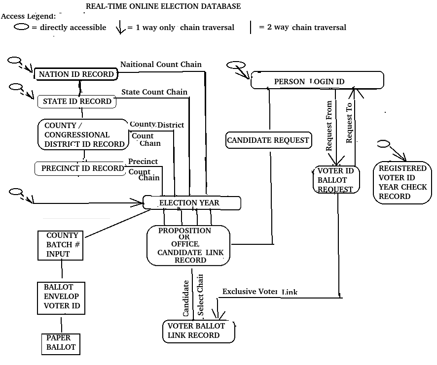
The database can be seen as divided into four sections:

1. The right  section represents the user logons & their online requests records for access & update permissions to the appropriate records in the database.    

2. The left hand side represents the administrator mini database which provides the tools required for validating logons, assigning voter-ids and setting up appropriate levels of update permissions for lower level logons.

3. The middle-left section represents the government’s organizational hierarchical levels from the top-down and associated election data.

4. The middle right section represents the linkages from a citizens’s request to:
a. a government office based upon his submission of a candidate requests,  or
b. access a ballot based upon his submission of a ballot request.
These requests are serviced  by state election administrators who are basically online voter registrars. 

Section 1 – USER LOGONS:

The right-hand side of the database map represents the user logon & identity part of the database & any requests they make. For privacy reasons, access to this section is restricted to the individual logon and any administrator. This is to protect a person’s voting record, as well as his profile. No other individual should be able to view how another person votes or have access to items used to identify the person.

Anybody can create a user logon with password,  regardless of citizenship.   In creating a logon, the user must submit his birth date  & state drivers license number or social security number. But it should be noted that drivers licenses & social security numbers by themselves are insufficient proof of citizenship, because such numbers are granted to citizens and non-citizens alike. Therefore, merely creating a logon does not automatically grant a voter-id which is required for obtaining access with update permissions to any other section of the database. The user without a voter-id number is strictly limited to their logon section in the database.

A voter-id number can be obtained by submitting a request to an administrator  in person or online, with proof of citizenship.  Proof of citizenship includes a passport or medicare number, a birth certificate or  naturalization papers, along with a picture. Such a  request can be in the form of  asking for: a) a voter-id or b) a candidate setup or a c) ballot setup, or d) administrator permissions . And until an existing administrator approves the request,  that person’s logon should not have any access or update permissions beyond their current status. 

Once a voter-id is obtained, the user’s logon request is linked to the the current year’s existing election data applicable to his request as a candidate or his ballot request. For as long as he has his voter-id, he will not have to resubmit his proof of citizenship. If he makes any changes to  what he submitted, including his birth date or drivers license, he may have to request a new voter-id number.   

Section 2 – THE ADMINISTRATOR MINI DATABASE  FOR SECURING THE ELECTIONS. 

Do you see the administrator mini database section on the far left? There you will see 3 record types connected similar to what was described previously in figure A , but with the elimination of the link chain between  the top two boxes & the addition of a 2nd link chain between the top and bottom boxes. One of these top-to-bottom link chains is for new voter-id requests, & the other is for approved voter-ids. And what was the middle box hybrid master has become a pure external master  noted as the “Birthday Chain Master” tying in to the lower voter-id detail record. The purpose of that record is to link together all voter-id records that have a common birth date making it possible to prevent two different voter ids being granted to the same person having two different logons. It also helps to identify potentially dead persons. It should also help to prevent the same person from voting in two different states during the same election. 

In the far left-hand section of the database schema is the voter-id database, aka, the administrator  mini database, which provides a unique number to specifically  identify each and every US citizen.  As previously stated, anyone can create a logon, citizens and non-citizens alike. But, based upon proof of citizenship submitted either in person or online,  the assignment of a voter-id  to a citizen person’s logon is critical in allowing that  user’s logon to have update-accessibility to  any portion of the election system database appropriate to that person’s level of responsibility.

Only citizens can approve voter-ids for other citizens. Please note that even all election administrators  must have validated  voter-ids tied to their logons, regardless of their governmental level of responsibility. But to begin, we must assume that all  election administrators do have valid voter-ids tied to their logons & will discuss later how they acquire administrative level permissions. But for now our focus is upon the management of a voter-id  database containing all voter-id records.  

Of first concern is who are the logons that will be allowed to access & manage  the  voter-id database. Because of their immediate closeness to the voting public, obviously all local state election officials will have update-access to the appropriate state organizational level within the database  & as  flagged in their logon by the update-access-level-indicator, aka, the “administrative-level-indicator”.  Precincts will be assigned to administrative-level-2. Level–3 is for city, level-4 for county & level-5 for state.

What about  levels 0 & 1? They are levels assigned to non administrators, ie, joe public, by the higher-level folks. When a user first creates his logon, it will be forced to level-0 which denies him from accessing any part of the election system database. Upon his request to an administrator & being approved as a citizen, he is given an active voter-id & his logon level will be changed to level-1.

Any of these state levels can accept a voter-id request and begin, if not finish, the approval & activation  of a validated voter-id. With the exception of being able to assist a level-0 request, each level will be confined to its own  level. So state administrators will not be able to override county, city or precinct administrators. 

State governments should not be updating their voter rolls based simply upon a DMV request.  Nor should states be issuing ballots without a would-be voter request. Only via state election administrators at the various state levels should be permitted to  give out ballots in electronic form  to people who have voter-ids. And if a would-be voter does not have a voter-id, he should be able to request one of the local state election administrator at the time  he applies to be a candidate or in requesting a ballot. The local state administrator should be able to assign the next voter-id number available, & create a new preliminary voter-id record containing the following data: 1) a record status flag initialized to pending status, 2) mandatory data including the requester’s logon id, birth date, & drivers license & 3)  data fields including passport id with flag, medicare id with flag, & social security id with flag should be defined and filled in if possible.  Then the local state administrator should attempt to validate the requester’s citizenship. If the local administrator cannot validate the would-be voter’s citizenship, then he should link the  preliminary voter-id record in a voter-id validation request chain to be reviewed by the feds who will approve it or reject it by tagging the record with an approved or rejected flag.

Federal administrator logons will be assigned to level-6 & include employees within the Federal Election Commission,  the US State Dept, the Medicare Admin, or the Social Security Admin. These are necessary because  any one of these federal agencies can validate the authenticity of a preliminary or existing voter-id record. In addition they should be validating each and every activated voter-id every four years.

Upon approval by at least the local state administrator or  one of the federal agencies, the would-be voter’s logon will be updated from level-status 0 to level-status 1 and his new voter id will be updated in his request record. When the voter dies, his logon will return to level-status 0.

Having identified the election administrators & their logons, what does their online real time voter-id system database schema, aka, the administrator mini database,  look like?

Section 3 – THE ORGANIZATIONAL HIERARCHY:

The middle-left part of the database represents the governmental hierarchy. In the governance of our national elections, the smallest entity is a precinct within a zip code, which is within the governance of a city, which is within the governance of a county, which is within the governance of a state, which also governs congressional districts & is within the governance of the feds. This organizational level structure is reflected in the left side of the database diagram where  each level is tagged with an update-accessibility level-indicator. The very top-level is the federal government which is tagged as update-accessibility level-6. Proceeding down through the levels, each lower level gets tagged with the  next  lower level indicator. As a consequence & as previously noted, we have level 6 being the national level, level 5 the state level, level 4 the county & district level, level 3 the city level, level 2 the precinct level. And again, this leaves levels 1 & 0 representing the individual user logon.  To be perfectly clear, this level indicator will be used to flag organizational administrative  areas of the database & to grant update permissions of those administrative areas to those user logons indicating the same level indicator. 

Section 4 – TYING USER LOGONS TO THE GOVERNMENT ORGANIZATION & ELECTION RECORDS:

The middle-right part of the database diagram deals with the people logon accessible record-types. As previously stated, any individual, regardless of their level, (federal, state, county, city, precinct or voter) should be able to create a logon in order to make an online voter-id/candidate/voter ballot requests. However, just because they have a logon does not mean they can access or update any other part of the right hand side of the database. Where it may be possible for a person to create multiple logons and create multiple requests, the database will contain administrator tools to help curtail any one single person from obtaining more than one means of having access to the right hand side of the database. Furthermore, upon creating their logon, it will be tagged with an accessibility level = 0 to indicate the logon has no valid Voter-ID and will not have access to any record in the right hand side of the database other than the logon & candidate/ballot request records.

With respect to the citizen logon level indicator, level-1 will indicate the citizen voter or candidate has a valid & current Voter-ID. Level-2 will indicate the citizen is a precinct only administrator. Level-3 will indicate a city only administrator. Level-4 will indicate a county & district administrator. Level-5 will indicate a state administrator. And level-6 will be a national or federal administrator. Administrators will have update accessibility to their own level and the next lower level, but only read accessibility to any other level above or below.

HOW TO GET A VALID VOTER-ID FOR YOUR LOGON:

Depending on the level of the request, the appropriate administrator would be able to confirm whether or not the requester has a current Voter-ID. If the requester does, then all the administrator has to do is create candidate or ballot record linkable to the request. But If the requester does not have a valid current Voter-ID, then he must submit proof of citizenship in his request. With this information, the administrator must check to verify it is okay to assign a new Voter-ID to the requester and then create candidate or ballot records linkable to the request. It should be that simple.

Of course, not every body may have a cell phone or computer. In this case they must go into the county registrars office to apply. And if they can’t do that, then a ballot notary is required.

FEDERAL DATABASE RESIDENCY & ADMINISTRATIVE RESPONSIBILITIES:

The database would be maintained on a federal computer, where the feds might initialize Voter-ID records from a cleaned version of the State Department’s passport system allowing only citizen records to be used, non-citizen records being excluded. In addition, the feds would initialize the Nation and State ID records for each state , these being fixed entities. And for each State ID, the feds would create backdoor level-5 sign-ons with passwords to be used by the state for its administrative duties. This is reiterated in the following.

A CASCADING INITIALIZATION OF THE ORGANIZATIONAL HIERARCHY:

Original access will begin at the national level-6. For database initialization purposes, a backdoor administrator level-6 logon will be provided to create the National-ID record. And from this backdoor level-6 logon it will be possible to change any level-0 logon to another level-6 or level-5 administrator logon once the level 0 logon owner submits proof of citizenship either in person or via the logon online candidate/ballot request process. Any level-6 administrator will create the State-ID records, along with creating a backdoor level-5 administrator logon for each state.

STATE RESPONSIBILITIES:

In a similar fashion, each state’s backdoor level-5 logon will be able to change any level-0 logon to another level-5 or level-4 administrator logon once the level 0 logon owner submits proof of citizenship either in person or via the logon online candidate/ballot request process. Any level-5 administrator will create the County-ID records & District-ID records, along with creating a backdoor level-4 administrator logon for each county.

COUNTY RESPONSIBILITIES:

In a fashion similar to the state, each county would setup City-ID records, along with creating backdoor level-3 logons to be used by city administrators in conducting its elections.

CITY RESPONSIBILITIES:

In a fashion similar to the county, each city may elect to setup Precinct-ID records, along with creating backdoor level-2 logons to be used by the precinct administrators.

OFFICE/PROPOSITION RECORDS:

Obviously for each level of governance from city on up there exists departments & offices with positions to be filled, some of which are filled via elections. And so each level of government is responsible for defining those positions to be filled via election. These are the Office-ID records, and each year some or all of them may have vacancies to be filled by candidates.

This brings us to the creation of a candidate-link record by the appropriate level administrator. And how do we determine that?
The office record should have a field that identifies its level.

CANDIDATE/BALLOT REQUESTS:

I have previous mentioned these record types before without being specific.

A CANDIDATE REQUEST will call out the specific Nation-ID, State-ID, County/ District-ID, & City-ID where applicable & the specific Office-ID. Assuming the would-be candidate is qualified & has a valid Voter-ID, the impacted administrator level will create a candidate link record for the year in question, thus establishing his candidacy.

It should be noted that there are times when there are non-candidate measures at the city, county, or state levels to be voted upon. These are identified as Propositions. They are identified in the same candidate link record-type which is accessible via the voter to the same candidate link record-type as used for candidate-to-office links.

A BALLOT REQUEST is simply a request to his lowest level of election administration to create links between his ballot request master & the candidate link records applicable to his geographic area.

VOTING:

The database is now ready for the voter to make his candidate selections by clicking the appropriate candidate-selection button in each appropriate voter-ballot-link record, at which time a write-permission lock is placed on the voter-ballot-link record. This would prevent anyone from changing candidate-selection button and the corresponding link to the selected candidate record.

POST VOTING RECORD ACCESS:

For secrecy/privacy purposes all cast voter-ballot-link records should be locked from updating by anyone other than the voter and as soon as they are counted. With this one exception, all should be able to view any record at any time, thus providing complete transparency and veracity of an election. In other words, everyone can look anywhere but not touch.

TALLYING UP THE TOTALS:

In addition, currency of vote tabulation is essential. As soon as a voter has locked his voter-ballot record, his vote should be counted and tallies by candidate should be made available. Washington DC should be connected to each state & have access to each state database for the purpose of rolling up ballot totals for each national candidate by state.

KEEPING THE VOTER-ID ROLLS CLEAN:

Currency of the voter rolls is essential and a responsibility of the feds. Voters who have died would have their Voter-ID record flagged as such. But aside from that, there are bad players who would try to vote more than once. This should be averted by looking out for duplicate Voter-ID and ballot requests in & across all states.


PROS:

What would be the advantages of an online real time election system?
First, the election should be completed within 2 days, if not sooner.
Second, the voter would cast his ballot directly into the database, thereby eliminating anybody other than the voter from touching his ballot.
Third, a voters ballot choices would remain unknown to anyone but the voter.
Fourth, since there is only one machine involved, auditing software should be comparatively, making it easy in identifying any other anomalies.

CONS:

There will always be some ding dong who insists on having a paper ballot which necessitates having a batch input system.

HOW TO READ THE DATABASE:

Let’s begin with an analogy in the form of a picture on paper representing an invoice containing a list of purchased items. The top line appears only once & contains information common to all items listed as purchased . The top line is the header, or “master” record. The items listed are “detail” records. Now consider a stack of invoices that all have the same format. They all have the same “master record-type” with the same “detail record-type”.

A database is an electronic file cabinet for all these invoice “record-types”. To be more specific in electronic terms, a “record” is a fixed length string of data broken into “data-fields”, all representing something or having some particular meaning, and a “record-type” is the representation of the collection of all records having a common fixed data content, format & key sort field different from all other records. To look a record-type is the same as looking at the format of a specific record. A record-type is a template or example of what a record looks like. (Note: the word “record-type” is used interchangeably with the word “record”).

Returning to the database diagram, each box represents a “record-type”. You will see boxes around the periphery that have a little short arrow pointing at the box headed by an ellispse, a square or an “x” . These are “External Master Record-Types” which are the basic entree points into the database via their unique id data-fields. The ellispe heading on the arrow means read accessible to all. The square means update accessible to administrators only. The “X” is exclusive to the citizen logon.

You will see that the nation record-type (of which there there is only one for the USA) is directly read accessible by anyone based upon its nation ID. You will also see that each state record-type is directly read accessible by all based upon its unique state ID. The same holds true for the election year and zip code record-types. Another external access point is via each individual citizen’s exclusive login point. Finally, there are three other administrative access points necessary for validating citizen requests.

Outside of the External Master Record-Types, all other record-types are Internal-Detail-Record-Types accessible only through “Link Chaining” which is shown by a link chain line connecting a higher level master box to a lower level detail box. You might notice that each state record is not only accessible as an external master record, but is also accessible via the “Link Chain” from the nation record. By “Link Chaining” I mean there is a link field in each master record-type that points to the first record within a detail record-type, which in turn has a link field that points to the next record within the same record-type, and so on until the last record of that record-type which may or may not point back to the original master records. Note that an internal detail record-type in one link chain can be a master record-type in another chain. Hence, a completely accessible hierarchy is achieved.

Referring to the database diagram, with respect to link chain traversal, the default direction of link chain traversal is always forward from master to the first detail record and from current detail record to the next. if there is no arrow pointing to a detail record-type, it means that the master record is retrievable from any detail record by continuing to traverse the chain to the last detail record which contains the link back to the original master record. However, if there is an arrow pointing to the detail record type, it means the last record in the chain has its next record link null, thereby making it impossible to retrieve the master record of the chain.

To complete the picture, given a nation id of USA, one could directly access the USA record & then traverse the state chain to access all the states within the USA. Similarly, one could access all the counties within a state by first accessing the state record & then traversing the county chain. And so on.

Today’s average browser-to-website user should not find this method of navigation too difficult to understand.

EARLIER POSTS:

The Real Threat: https://www.aaarrrg.com/wordpress//?p=3161

The Virtual Precinct: https://www.aaarrrg.com/wordpress/?p=2632

Categories
TECH

INTERNET BASICS

Rules For Securing Your Own Email:

1. You can’t secure your email if you use a cloud email service except via the tools provided by the email service

2. Your router and your firewall are all you need to secure your own email server. This requires a simple understanding of how internet addressing works.

First, understand that a domain name has no real significance in addressing. All addressing boils down to an IP NUMBER and a PORT NUMBER. The ip number, v.w.x.y, is the equivalent of a building address. The port number, z, is the equivalent of an apartment number. The two are expressed together as v.w.x.y :z.

With respect to email, the port numbers 25 and 587 are used to send email. The port numbers 143 and 993 are used to retrieve email in an IMAP fashion as opposed to 110 and 995 in a POP fashion.

So how do I block out unwanted hackers or spammers. First, my ROUTER must block out all unused ports, ie, empty apartment numbers. But it has to let through all traffic to the ports in use, ie, ports 25 and 587. This is accomplished via PORT FORWARDING, which is a function in your router to direct traffic addressing a port to its ultimate computer program, ie, destination.

Secondly, I have to use the firewall to block out the ip numbers (addresses) of unwanted visitors trying to hack my computer. These are found by inspecting the email server log. The hackers become quite obvious in the log.

Oh, wondering about my ip address? It is the ip assigned to me by my internet service provider. The isp forwards all internet traffic calling out this ip address to my router which begins sorting out what ports go to what computers I have on my local network.

What is my local network? That’s everything I have wifi-ed or physically attached to my router. And how do ports get connected to programs? Once the router directs a specific port to a specific computer, the programs (apps) have to be told what ports to “LISTEN” to.

So what has domain naming got to do with anything? First, we have to know that a domain is a fancy word to identify the digital hardware and software resources belonging to a specific owner. So I have two main domains that are identified as trcooper.com and aaarrrg.com. These names get resolved (translated) into the ip addresses where they reside(hosted) by an INTERNET DOMAIN NAME SERVER (DNS) which is nothing more than a lookup service, like a phone book or 411.

So, getting back to the actual residency of my domains, the trcooper.com main domain is on the GoDaddy computers, whereas aaarrrg.com is on my home computer. These are where my websites reside.

But what about my email server? Where does it reside? This is where SUB-DOMAIN naming comes in. My email server resides on my home computer which is identified as a sub-domain of trcooper.com and identified as mail.trcooper.com. The dns server will direct all traffic calling out mail.trcooper.com to my home computer and not the GoDaddy computer. So it’s all like a company that has multiple addresses.

The only thing I have not covered is encryption which provides the ultimate security in digital communication. Another word that goes flying around is the word “protocol”. I find this word being so widely abused that it has almost lost its meaning. Basically, it is a predefined way in which two communicants can verify they are speaking to the right person.  One of the first protocols was the “ack”- “nak” , acknowledge- no acknowledge. Different strokes for different folks. Ground control to major Tom. At the current time, it appears as though a protocol called TLS (transport layer security) is replacing SSL (secured socket layer) in two-way digital communications.

Categories
COMMON SENSE SCIENCE SOLUTIONS TECH

The DIRECTION OF MULTIPLICATION

A. THE MEANING OF DIRECTION & SIGNAGE:

   We humans see ourselves in terms of position: vertical upright,
   horizontal on back, & horizontal on side.  These being our most
   common positions relative to Earth, they become the  3  basic
   dimensions that are seen as  3 linear axes orthogonal (at right
   angles) to each other. Furthermore, we think of measurable
   increments along each axis as being in the positive or negative
   direction depending upon their position relative to a zero point
   on the axis.   Such a concept gives us a 3-dimensional reference
   system that we see as absolute, albeit not necessarily so.    

   In mathematics unfortunately the plus and minus signs have two
   different meanings, depending upon the position relative to an
   operand. When touching an operand, it means the value of the
   operand is in the positive or negative direction along a linear axis.
   But it can also mean to add or subtract the operand in the absence
   of an explicit operator between two numbers.  And in the absence
   of a touching sign, the default is in the positive direction. When
   not touching an operand, it means addition or subtraction
   between two operands, ie,  it becomes an operator. So in an
   expression, there can be both directional signs and operational
   signs.

   As a side note & not relevant to this discussion, a minus sign in
   front of an exponent means to raise the reciprocal of the base to
   the power indicated by the exponent.


B. IMAGINARY NUMBERS:

   The imaginary number, i, is said to be the square root of -1 which
   is impossible, because according to current convention, there is no
   number multiplied by itself one time that yields a negative number.
   Lacking the ability to determine a numeric value, the square root
   of -1 is assigned the variable, “i” & complex numbers are
   mathematical expressions containing  “i”. A complex number is of
   the form (+or-)a +  (+or-)b * i, where “a” is the numerical offset,
   “b” is the numerical multiplicand, & “i” is the Multiplier. It is rare
   to see i * b, where “i”, as the Multiplier, precedes “b”, as the
   multiplicand. But that is going to change in this writing, as we
   shall soon see.


C. THE RULES OF MULTIPLICATION:

   The aforementioned indeterminate problem of not being able to
   evaluate “i” arises from the fact that mathematicians established
   long ago that A MINUS NUMBER TIMES A MINUS
   NUMBER SHOULD BE POSITIVE.  Furthermore, they
   established that THE PRODUCT OF TWO OPPOSITELY
   SIGNED VALUES SHOULD BE NEGATIVE. These
   conclusions arose due to the distributive law of mathematics.
   Let me state here my belief that when it comes to groupings
   via ( ..), the order of operations should dictate that expressions
   within a group should be evaluated first. But I will not quibble
   over the distributive law.


D. CURRENT MULTIPLY OPERATIONS IN USE:

   These current-day conventions affecting a change in value
   resulting from multiplication can be expressed as follows:

   Let:
            M = multiplier/operator

             m = multiplicand/operand

              “*” means times,
              (not to be confused with “**” which means exponent of)

             R = resulting product


   1. THE  PRODUCTS OF ACCUMULATIVE
       MULTIPLICATION:

      Accumulation Of Positives:
         Plus times Plus = Plus
             +M * +m  =  +R
              Interpretation:
                     Add +m  to the current value  M times.
                  OR GRAPHICALLY,
                     Relative to the current point,
                     go right M times in increments of |m|.  
               Example:
                   +3 * +2 =  +2 + 2 + 2 = 6

      Accumulation Of Negatives:
         Plus times Minus = Minus
            +M * -m  =  -R   
            Interpretation:
                   Add -m  to current value M times.
                OR GRAPHICALLY,
                   Relative to the current point,
                    go left M times in increments of |m|.  
             Example:
                +3  *  -2  =   0  + ( –  2  – 2  – 2)
                                =  0 + – ( 2 + 2   + 2)   =   -6


   2. THE  PRODUCTS OF DECUMULATIVE
       MULTIPLICATION:

      Decumulation Of Positives:
         Minus times Plus = Minus  
            -M * +m   =  -R
            Interpretation:
                Subtract +m  from the current value  M  times..
             OR GRAPHICALLY,
                Relative to the current point,
                go left M times in increments of |m|.  
             Example:
                 -3 * +2  =   0  +   -( 2 + 2 + 2)   =    – 6

      Decumulation Of Negatives:
          Minus times Minus = Plus
             -M * -m  =  +R
             Interpretation:
                  Subtract -m  from current value  M  times.
               OR GRAPHICALLY,
                  Relative to the current point,
                  go right M times in increments of |m|.
            Example:
               -3 * -2  = – ( -2) – (-2) – (-2 ) 
                           =  + 2 + 2 +2 = +6 

   Observe that I have identified two different types of multiplication,
   “accumulative” and “decumulative”. I make this distinction
   because accumulative  multiplication requires repetitive addition,
   where decumulative multiplication requires repetitive subtraction.

   Also, we note that the sign of the product resulting from the
   repetitive multiplication of a negative multiplicand  alternates
   between + on even repetitions & – on odd repetitions.  In other
   words, a successive number of subtractions of a negative number
   from itself ALTERNATES BETWEEN + & -.  This alternation
   does not appear anywhere else.  So this behavior is seen as
   unusual. 


E. RECONSTRUCTING THE PICTURE OF MULTIPLICATION:

   By insisting that the Multiplier always occurs in front of the
   multiplicand, we can clearly see that, among other things, a
   negative Multiplier means decumulation, whereas a positive
   Multiplier means accumulation. Aside from this fact, we might
   speculate that there could be other meanings in addition. What
   those could be, we are about to find out. 

   Moving on, we might assert that the Multiplier,M, reside on an
   M-axis different from the multiplicand,m, on a separate m-axis,
   with the two axes intersecting each other orthogonally at right
   angles. So the visual graphic of the Multiplier in relation to the
   multiplicand becomes a 2-dimensional planar picture with each
   axis having its own set of + & – directions, rather than just a
   simple 1-dimensional linear graphic.

             THIS                                  NOT JUST THIS

             m-axis
                  |  +                                                                              
       – ——0——- + M-axis        –  ———0———+ M & m
                  | –                              (We are not just talking candy here)

   Given this distinction, we can now begin to think in terms of:

      VECTOR CROSS-MULTIPLICATION,
          (aka, CROSS-MULTIPLICATION
               or
               CROSS-COMPUTATION 
               or
               X-MULTIPLICATION) ,

   versus

      VECTOR DOT-MULTIPLICATION,
          (aka, DOT-MULTIPLICATION
                or
                DOT-COMPUTATION   
                or
                *-MULTIPLICATION
                 or
                 SCALAR-MULTIPLICATION) .

   The difference is as follows.

   Vector dot multiplication results in a simple 1-dimensional product
   (called the dot-product) that resides on the same axis as the
   Multiplier & multiplicand. Up to now, current conventional
   multiplication has always been equivalent to vector dot
   multiplication for both accumulative and decumulative
   multiplication. But that is about to change, as we are about to
   change decumulative multiplication from vector dot to vector
   cross multiplication. The mathematical expression for computing
   the vector cross product is given as:

    R = M * m

   Vector cross multiplication results in a  product (called the
   cross-product) that is uniquely identified with a direction which
   is orthogonal to directions identified by the M-axis & the m-axis.,
   & whose numerical value is the simple product of the two
   numerical values further multiplied by the sine of the smallest
   angle, @, between the two vectors, M and m.  The mathematical
   expression for computing the vector cross product is given as:

   R = M X m = M * m*  sine(@) .

   So we now have two methods of multiplication, with
   cross-multiplication giving us a clearer 3-dimensional/directional
   picture shown as follows.

                   + m-axis              + R-axis  = CROSS PRODUCT AXIS 
                            ^                        /\
                             |                      ‘ 
                             |                  ‘             
                             |            R1 = (M1 X m1) * sine(90) /
                           m1       ‘     
                              |    ‘
      -M————–0———— M1 ——–> + M-axis
                        ‘     |    @ = -90   
                    ‘         |
                ‘             |
            ‘                 |
      -R                  -m   

   We now proceed to examine the deeper meanings of the
   cross-multiplication method.  


F. ABOUT THE ANGLE, @,  BETWEEN M & m.

   We’ve started out saying that M-axis was orthogonal to
   m-axis for the sake of simplicity. But the cross-product
   approach says that such is not always the case when it comes
   to vectors, because @ can take on any value between +90
   degrees and -90 degrees as the shortest path between the
   sides of the angle. And this has consequences for both the
   numerical value of the resultant, R, its dimension & its
   positive versus negative directions.        

   Before we go any further, we need to have a clear understanding 
   of how we view angles from a fixed observation point. Then we
   need to know what the sine of an angle is. And finally, we can
   discuss what role the of the angle between the Multiplier &
   multiplicand might be.     

   1. ABOUT PLUS & MINUS ANGLES:

       Envision the face of your clock where the M-axis is a straight
       line running from 12 to 6 in a negative direction & the m-axis
       is a straight line running from 9 to 3 in a positive direction.
       Progressing clockwise, we consider 12 o’clock to be +0
       degrees, & relative to it we recon 3 o’clock to be +90 degrees,
       6 o’clock to be +180 degrees, & 9 o’clock to be  +270 degrees.
       But progressing counter-clockwise from 12 o’clock, we
       consider +270 degrees to be -90 degrees & +180 degrees
       to be -0 degrees. So in this scenario, 12 o’clock is the reference
       side of any angle from it. And because we have aligned the 
       M-axis with 12 o’clock, the M-axis is also the reference side
       of any angle at which the m-axis intersects it.  Furthermore,
       should the M-axis be in a direction other than 12  o’clock,
       then the M-axis should remain the reference side of the 
       angle, @.  

       Therefore, the plus or minus direction of the angle,@,  between
       the M-axis and the m-axis depends upon whether or not we go
       clockwise or counterclockwise from the M-axis to the m-axis.
       And the shortest path from M to m will dictate whether we 
       proceed clockwise or counterclockwise from M.

   2. ABOUT THE SINE OF AN ANGLE:
       Now what about the sine of @? Without going into too much
      detail about what is meant by the sine of an angle, it is enough
       to say that the sine( +0  degrees) is +0, the sine(+90 degrees) is
      +1, the  sine(-0 degrees) is -0, & the sine(-90 degrees) is -1.
      So the sine of an angle acquires the same sign as the sign of the
      angle. If the angle is negative,  its sine is negative. If the angle is
      positive, its sine is positive.

   3. WHICH WAY JOSE, PLUS OR MINUS?:
       We now have to determine in what direction the product
       points, plus or minus, along  the resulting orthogonal axis. 

       Traditional vector math calls for the application of the RIGHT
       HAND THUMB RULE.  Finding this to be a little too
       nebulous to explain, I will only mention that the index
       finger should be the multiplicand. I leave it there.

       As an option, I would suggest discounting the sign of the
       Multiplier and applying the sign arising from the sine(@) 
       to the sign of the multiplicand to determine the sign of the
       resultant.  


G. REDEFINING ACCUMULATIVE  VS DECUMULATIVE
   CROSS-MULTIPLICATION:

   Having identified two different, but similar forms of
   multiplication, we now ask,”Are we using the correct form
   of multiplication for each?”. After all, we see some unexplainable
   differences between decumulative & accumulative operations.
   So let’s try applying vector cross-computation to multiplication
   instead of dot-computation. 

   We can now see that cross-multiplication not only results
   in a product pointing in an orthogonal direction away from 
   the directions of the Multiplier & multiplicand, but can
   yield an absolute value entirely different from today’s
   conventional multiplication, especially if the sine(@) is
    other than +1 or -1. Therefore, we ask “Which value(s)
   +1 or -1  would yield the same results as todays
   multiplication”.

   The answer(s) are clear. For accumulative
   multiplication, we need a sine(@) = +1, ie, @ = +90.
   For decumulative multiplication we need sine(@) = -1,
   ie. @ = -90. With this understanding,  we now modify the
   current conventions by simply replacing  the * operator with
   the X operator and adding the (sine @),   making @ = +90
   for  accumulative  & @ = -90 for decunulative
   multiplication. 

   Let:
            M = multiplier/operator

            m = multiplicand/operand

            “*” means times,
            (not to be confused with “**” which means exponent of)

            “X” means vector cross multiplication,
            (not to be confused with  variable “x” )

            “@” is the smallest angle between the M-axis & m-axis.
                    It is plus (+) if the shortest distance
                    from the M-axis to the m-axis is clockwise.
                    It is minus (-) if counterclockwise.   

             R = resulting product


   1. ACCUMULATIVE CROSS-MULTIPLICATION:
       For accumulative multiplication, +90 degrees is appropriate.
       In order for the resultant product, R, to become the same
       value as determined by vector dot multiplication, the value
       of sine(@) must equal +1, which means the angle, @, between
       the +M-axis and +m-axis must be  +90  degrees.
        @ = +90,   sine(+90) = +1 

      Accumulation Of Positives: 
         Plus times Plus = Plus 
         R =  +M X (+m)
              = |+M| * (+m) * sine(@) 
              = |+M| * (+m) * sine (+90) 
              = |+M| * (+m) * (+1)
              =  |+M| * (+m)
              = + (M * m)

      Accumulation Of Negatives:
         Plus times Minus = Minus 
         R =  +M X (-m)
              = |+M| * (-m) * sine(@) 
              = |+M| * (-m) * sine (+90) 
              = |+M| * (-m) * (+1)
              = |+M| * (-m)
              = – (M * m) 

   2. DECUMULATIVE CROSS-MULTIPLICATION:
      For decumulative multiplication, -90 degrees works.
      In order for the resultant product, R, to become the same
      value as determined by vector dot multiplication, the value
      of sine(@) must equal -1, which means the angle, @, between
      the +M-axis and +m-axis must be  -90. 
      @ = -90,   sine(-90) = -1

      Decumulation Of Positives: 
         Minus times Plus = Minus 
         R =  -M X (+m)
              = |-M| * (+m) * sine(@) 
              = |-M| * (+m) * sine (-90) 
              = |-M| * (+m) * (-1)
              =  |-M| * (-m)
              = – (M * m)

      Decumulation Of Negatives:
         Minus times Minlus = Plus 
         R =  -M X (-m)
              = |-M| * (-m) * sine(@) 
              = |-M| * (-m) * sine (-90) 
              = |-M| * (-m) * (-1)
              = |-M| * (+m)
              = + (M * m)


   Note that I did not recognize or apply the sign of the Multiplier. It
   was unnecessary when the sine(@) was included. Of course, I
   could have made @ = +90 for the decumulative operation. But
   then there still needed to be some explanation for the differences
   from accumulative cross-multiplication.


H. THE MYSTERY OF THE FLIP-FLOPPING RESULTANT: 

   1. ABOUT  SUCCESSIVE MULTIPLICATIONS.: 
       The fact that the resultant product of M1 X m1, R1, always
       resides in the direction orthogonal to the plane of the M-axis/
       m-axis, only one possible direction is left in which  R may
       reside, that direction being identified as the R-axis. And if that
       resultant  product, R1, now becomes the multiplicand, m2, of
       a 2nd such computation involving a new M2, then the direction
       of the new resultant  product, R2, must be on the same  axis as
       the previous multiplicand, m1. And  if that product, R2,
       becomes the next multiplicand  m3, on a 3rd such computation,
       then the direction of the new resultant product, R3, must be in
       the same direction as R1.  In other words, given a succession
       of repetitive vector cross-multiplications & where the
       resulting product becomes the next multiplicand, the R-axis
       switches positions with the m-axis & reverses its negative &
       positive directions.          

   2. REPETITIVE
       DECUMULATIVE CROSS-MULTIPLICATION 
       OF NEGATIVE  REAL NUMBERS:

       The placement of the product appears as a positive on the 
       R-axis & as a negative on the m-axis  in alternating order
       due to the right-hand thumb rule flip-flopping with each
       iteration of computing the cross-product.

       This explains why a repetitious negative times a negative 
       equals a positive R1 on the R-axis, followed by a negative
       R2  on the m-axis,  followed by a positive R3  back on the 
       R-axis. It gives the appearance of a pulsating R-axis
       acting as a binary switch between + & -. 

   3. RAISING IMAGINARY  -i TO THE Pth POWER.

       If we conduct a succession of decumulative-cross 
       multiplications of -i , assuming @ = 90 degrees, we get:

        (Cycle begins)

       (-i)**2 = -i  X -i   =  +i**2  =  -1   ( R1 to the R-axis)
                              ______________|                    
                              V
       (-i)**3 = -i X -1  =  -1 X -i  = +i     (R2 to the m-axis)
                               ______________|                    
                               V
        (-i)**4 = -i X +i  =                   +1   (R3 to the R-axis?)
                               ______________|                    
                               V
        (-i)**5 = -i X +1  =                    -i   ( R4 to the m-axis?)
                                                             |
        (Cycle starts over)                       |               
                               _______________|                    
                               V
        (-i)**6 = -i X  -i   =                    -1  (R5 to the R-axis?)                                                             

        Powers of (-i) confirmed by internet.

        Of great interest here is the observation that the successive 
        multiplications oscillate between real rational numbers and
        imaginary irrational + & – i.  We must ask, ” is i the basic 
        unit of measure in the world of irrational numbers?”. 

        NOTE:  e**i*pi = -1     where e is Eulers irrational constant.


I. CONCLUSIONS:

   1. We have identified two distinct forms of multiplication, ie,
       accumulative vs decumulative multiplication, the difference
       being the accumulative form is a series of additions whereas
       the decumulative form is a series of subtractions. 
       The sign of the Multiplier, M, identifies which form it is.

   2. We have identified two methods of multiplication, dot-product
        multiplication and cross-product multiplication, We have
        adopted  cross-product as the proper method to be used in both
        accumulative and decumulative multiplication. In doing so,
        we recognize the angle between  between the Multiplier &
        multiplicand to be +90 degrees for accumulative multiplication
        as opposed to -90 degrees for decumulative multiplication. 
        As a result, the sign of the Multiplier does not enter into the 
        computation of the product. 

    3. The angle, @, from the Multiplier to the multiplicand is
           normally +90 degrees in order to make the sine(@) = +1,
           thereby confirming that the M-axis is normally orthogonal
           to the m–axis, albeit not eliminating other possibilities for
           values of angle @, resulting in a wide variety of product
           values and plus or minus direction.

   4. The fact that both operands, M & m,  reside on a different axis
       as vectors means that the communitive law no longer applies,
       disproving the idea that a minus times a plus is the same as
       a plus times a ninus. It becomes like saying
       6 cats are the same as 6 dogs.

   Nothing has been done to change anything outside the realm of
   conventional arithmetic & mathematics.  Rather we have found
   old precepts to be applied in new ways to open the door to
   understanding some areas that left us perplexed. As a result, we
   have uncovered a new way of perceiving multiplication, resulting
   in the identification of decumulative multiplication as distinct
   from traditional accumulative multiplication. We have  uncovered
   some interesting details about how we can graphically interpret
   multiplication that involves what we call “direction” Finally, we
   have shed important new light on an entity that has kept its
   meaning hidden from us for so long,
   ie, the imaginary number,  “i”.